Marble Staircase Measurement & Installation Guide
Professional guide to measuring, designing, and installing natural stone stair treads
For most people, climbing stairs is not the most pleasant experience. But staircase design can be transformed through the choice of materials. Natural stone is widely used in interior spaces, but unlike other materials, stone cannot be easily adjusted, repositioned, or reshaped after cutting. This means that measurement, fabrication, and installation must be done correctly the first time. This guide covers professional methods for marble staircase measurement and installation.
Measuring Stair Treads
Using a standard return staircase (first floor to second floor) as an example, stair tread measurement follows three key references: horizontal lines, vertical lines, and cross-axis reference lines.
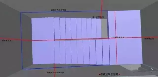
Simulated concrete foundation layout diagram
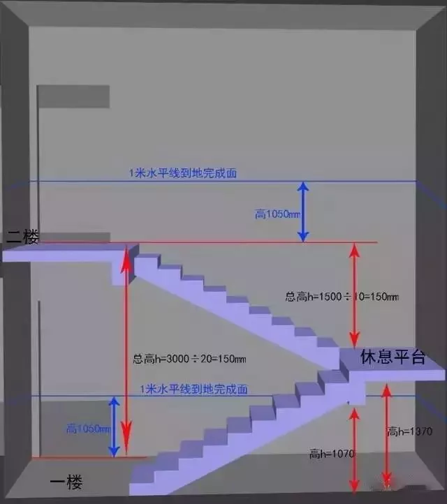
1. Horizontal Reference Line
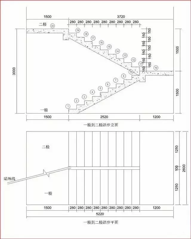
The horizontal line is used to measure the base height of each tread. Total height = 3000mm, including the landing, with 20 steps total. The 1-meter finished floor level (FFL) line is the standard reference used in ordering and design drawings.
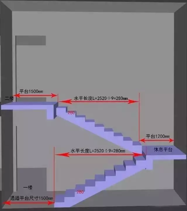
2. Vertical Reference Line
During measurement, snap a chalk line along the edge of the treads or use a laser level to establish a vertical reference. This is used to measure the total tread width and the length and width of landings. In the diagram below, the upper and lower landings are both 1500mm wide, with the intermediate landing at 1200mm.
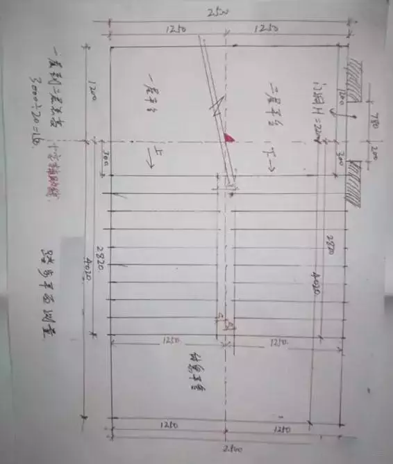
3. Cross-Axis Measurement
A hand-drawn measurement diagram best illustrates this technique. The cross-axis method is particularly important for site layout and applies equally to stair tread measurement.
CAD Drafting & Design
Using the measurements above, here is how CAD drafting and design is done:
Step 1: Create CAD Drawing from Measurements
CAD software is widely used in the stone industry for precision dimensioning. The elevation view shows total height of 3000mm, 20 steps total, horizontal run of steps 1-9 and 11-19 totaling 2520mm, and tread width of 1250mm. (Stone thickness: 15mm)
Step 2: Detailed Stone Design
The stone designer develops detailed shop drawings based on field measurements. Fabrication and installation both follow these drawings, requiring strong technical knowledge of both installation and fabrication techniques.
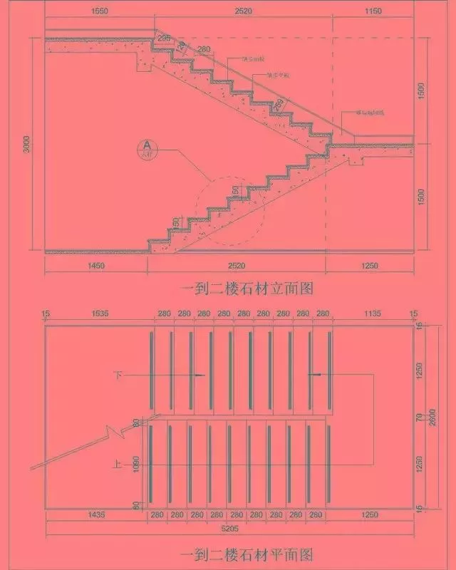
Detailed stone tread CAD drawing showing standard design specifications
Key specifications: The finished marble surface sits 50mm above the concrete base for treads, and 35mm for risers. The tread nosing projects 15mm beyond the riser with a 5x5mm bevel. Anti-slip grooves are 3mm wide and 2mm deep. (Stone thickness: 15mm)
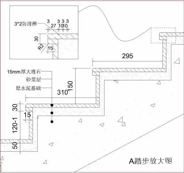
Detail A – Enlarged view showing the riser sitting on top of the tread, with the thickened edge supporting the riser to prevent detachment and edge chipping
The stone details are clearly visible: the riser sits on top of the tread panel. The riser also supports the thickened edge strip, preventing long-term detachment and reducing stress on individual panels. The total finished height of the riser is 150mm. When ordering, the riser should be cut to 119mm (120mm minus 1mm). The 1mm allowance provides adjustment during installation, as perfectly tight joints are impossible. Without this allowance, 20 steps would accumulate 20mm of error.

Stone cutting diagram (stone thickness: 15mm)
Based on the CAD drawing: Tread panel = 1235 x 310mm (finished width). Riser panel = 1235 x 119mm. Thickened edge strip cutting: 1250 x 30mm and 310 x 30mm.
Order Calculation Formula
- Tread ordering size, L = 310mm
- Concrete base tread width, a = 280mm
- Nosing projection, b = 15mm (recommended range: 15-20mm, do not exceed 20mm)
- Riser overlap dimension, T = 119mm
- Thickened edge strip height, d = 30mm
- Concrete base height, j = 150mm
Result: Tread 310 = 280 + 15 + 15, Riser 119 = 150 – 30 – 1
Alternative Installation Methods
Installation Method 2
Similar to Method 1, but the thickened nosing covers the horizontal joint between the riser and tread. In this method, the riser calculation only subtracts the tread panel thickness (15mm). However, this method is more prone to the thickened strip detaching and edge chipping over long-term use.
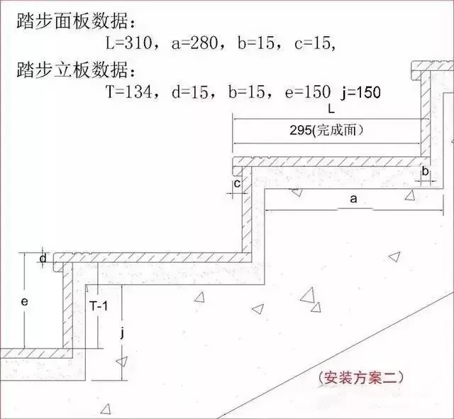
Installation Method 2 – thickened nosing covers the riser joint
Tread L = 310mm, Riser T = 119mm, Panel thickness d = 15mm (only subtracts tread thickness)
Result: Tread 310 = 280 + 15 + 15, Riser 134 = 150 – 15 – 1
Tread dimensions unchanged, riser dimensions adjust accordingly.
Installation Method 3 (Slot Method)
Similar to Method 1. This method is recommended only when the stairs have baseboards or skirting boards on both sides. If one side is exposed, the thickened edge finish is not optimal.
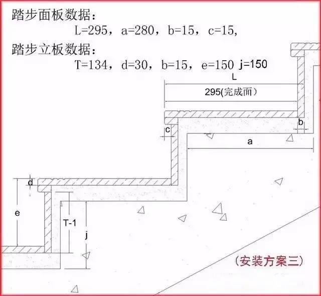
Installation Method 3 – Slot method suitable for stairs with baseboards on both sides
Tread dimensions adjusted accordingly.
Key Takeaways
- Measure twice, cut once — stone cannot be easily adjusted after fabrication
- Always include a 1mm adjustment allowance on riser heights to prevent cumulative error
- Method 1 is recommended for most installations as it provides the best long-term durability
- Anti-slip grooves (3mm wide, 2mm deep) are essential for safety on marble treads
- Stone thickness of 15mm is standard for stair applications